

how to use hvac manifold gauges pdf
Confused by HVAC manifold gauges? Get a clear, concise PDF guide from Moupma! Learn to read & use them like a pro – troubleshooting & maintenance made easy.
Understanding HVAC Manifold Gauges
HVAC manifold gauges are crucial tools for technicians, connecting to high and low-side service ports to measure system pressures, aiding in diagnosis and refrigerant management.
What are HVAC Manifold Gauges?
HVAC manifold gauges are essential diagnostic tools used by technicians to assess the performance of heating, ventilation, and air conditioning systems. These gauges aren’t single units; they’re typically a set featuring two gauges – one for measuring high-side pressure and another for the low-side. They connect to the system via service ports, providing critical readings about refrigerant levels and system operation.
Essentially, they allow technicians to determine if a system is properly charged, identify potential leaks, and evaluate the overall health of the refrigeration cycle. Understanding these gauges is fundamental for effective HVAC service, enabling accurate diagnosis and efficient repairs. They are vital for tasks like vacuuming, charging, and leak detection, ensuring optimal system performance.
Types of Manifold Gauge Sets
Manifold gauge sets primarily come in two main types: single-valve and dual-valve configurations. The dual-valve set, more common for professional use, features separate valves for the high and low sides, offering greater control during servicing. These allow independent isolation of each side of the system.
Simpler single-valve sets are available, but offer less precision. Furthermore, sets are categorized by the refrigerants they support. Traditional sets work with R-22, while newer systems, utilizing R-410A, require specialized manifolds designed for higher pressures. Choosing the correct set is crucial; using an incompatible manifold can lead to inaccurate readings and potential damage to the equipment. Always verify compatibility before use!
Preparing to Use HVAC Manifold Gauges
Proper preparation involves closing both manifold valves clockwise, attaching couplers, and identifying the high and low-side connections before beginning any service work.
Pre-Service Instructions: Closing Valves
Before connecting the manifold gauge set to an HVAC system, a critical first step is ensuring both the high and low-side valves are completely closed. This is achieved by turning both the High and Low knobs on the manifold clockwise until they are firmly seated.
This precaution prevents accidental refrigerant release during connection, safeguarding both the technician and the environment. Failing to close the valves could result in a sudden pressure surge or loss of refrigerant from the system.
Double-checking the valve positions is highly recommended. A properly closed valve will prevent any flow between the manifold gauges and the system until intentionally opened for testing or service.
Connecting the Gauges to the System
After verifying the valves are closed, carefully attach the high and low-side couplers to the corresponding service ports on the HVAC unit. The high-side port is typically smaller, while the low-side is larger. Ensure a tight, leak-proof connection by firmly screwing on the couplers.
Avoid cross-threading the connections, as this can damage the service ports. Once connected, briefly “crack” open both high and low-side valves to purge any air from the gauge hoses. This minimizes inaccuracies in initial pressure readings.
Always inspect the connections for any signs of leakage before proceeding with system evaluation. A proper connection is vital for accurate diagnostics and safe operation.
Identifying High and Low-Side Connections
Distinguishing between high and low-side connections is fundamental. The high-side port, connected to the compressor discharge, is generally smaller in diameter and often color-coded red. This side exhibits significantly higher pressures due to the compressed refrigerant.
Conversely, the low-side port, linked to the evaporator return, is larger and frequently color-coded blue. It displays lower pressures as the refrigerant absorbs heat. Incorrect connection can damage the gauges and provide false readings.
Referencing the unit’s service label or documentation is crucial for confirmation. Always double-check before opening any valves to prevent potential system damage or personal injury.
Reading HVAC Manifold Gauges
Interpreting pressure readings from the gauges—high and low sides—is vital for diagnosing HVAC system performance and identifying potential refrigerant issues.
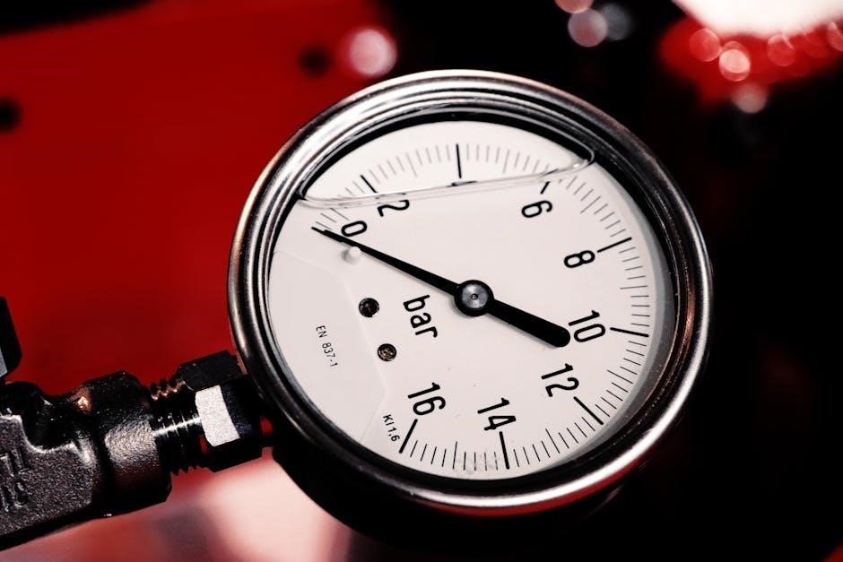
Understanding Pressure Readings
Pressure readings on the HVAC manifold gauge set provide critical insights into the system’s operation. The high-side gauge indicates the pressure after the compressor, reflecting cooling capacity and potential restrictions. Conversely, the low-side gauge shows pressure before the compressor, revealing refrigerant flow and evaporator performance.
Normal ranges vary based on refrigerant type and ambient temperature; consulting a pressure-temperature (PT) chart is essential. Abnormally high pressures can signal overcharging, a condenser issue, or airflow restriction. Low pressures might indicate undercharging, a refrigerant leak, or a faulty evaporator. Accurate interpretation, combined with temperature measurements, allows technicians to pinpoint problems efficiently and ensure optimal system functionality.
Interpreting Superheat and Subcooling
Superheat and subcooling are vital measurements refining system diagnosis beyond simple pressure readings. Superheat, measured on the low side, indicates how fully the refrigerant has vaporized before reaching the compressor, preventing liquid slugging. Low superheat suggests overcharging or a malfunctioning TXV. Subcooling, measured on the high side, reveals how much the refrigerant has condensed into a liquid after leaving the condenser, ensuring efficient cooling.
Proper superheat and subcooling values, determined by the refrigerant type and system design, confirm correct refrigerant charge and component operation. Deviations signal potential issues like restricted airflow, metering device problems, or refrigerant leaks, guiding technicians towards precise repairs and optimal system performance.

Using Manifold Gauges for Specific Tasks
Manifold gauges facilitate vacuum testing, leak detection using pressure changes, and precise refrigerant charging, ensuring optimal system performance and efficiency for HVAC professionals.
Performing a Vacuum Test
A vacuum test is essential before charging refrigerant, removing air and moisture from the HVAC system. First, ensure both manifold gauge valves are closed. Connect the manifold gauge set to the system’s service ports, then open the low-side valve to initiate evacuation with a vacuum pump.
Monitor the vacuum gauge; a deep vacuum (typically below 500 microns) indicates a successful evacuation. After reaching the desired vacuum level, close the manifold gauge valve, then stop the vacuum pump. Observe the gauge for at least 10-15 minutes; any pressure rise suggests a leak. If the vacuum holds, proceed with refrigerant charging. Remember to check the vacuum with the gauge manifold valve closed before stopping the pump!
Checking for Refrigerant Leaks

Refrigerant leaks compromise system efficiency and environmental safety. After evacuation, before charging, pressurize the system with a small amount of nitrogen – typically around 100-150 PSI – using the manifold gauge set. This provides a safe testing pressure.
Employ a gas leak detector, waving the sensor along all refrigerant lines, connections, and service ports. Listen for hissing sounds, another indicator of a leak. Alternatively, use a leak detection solution designed for refrigerant systems. Any bubbling signifies a leak point. Address leaks immediately with appropriate repair methods, then re-test before proceeding. A torque wrench ensures proper fitting tightness, preventing future leaks.
Charging Refrigerant into the System
Charging refrigerant requires precision. With the system evacuated and manifold gauges connected, slowly open the low-side valve on the manifold, introducing refrigerant. Monitor both high and low-side pressures closely, referencing the unit’s nameplate for correct operating pressures.
An electronic refrigerant charging scale ensures accurate amounts. Observe superheat and subcooling readings to fine-tune the charge. Avoid liquid refrigerant entering the compressor; crack open the high-side valve briefly to allow vapor to pass. Use a charge hose appropriate for the refrigerant type (R410A requires specific hoses). Regularly check for leaks post-charge, and document the refrigerant added.
Essential Tools for HVAC Work
Essential HVAC tools include a gauge manifold, charge hose, leak detector, vacuum pump adapter, flare tool, and torque wrench for efficient system servicing.
Gauge Manifold
The gauge manifold is the central component, featuring high and low-side pressure gauges, valves for controlling refrigerant flow, and couplers for connecting to the HVAC system. It allows technicians to monitor pressures during various processes like evacuation, leak detection, and refrigerant charging.
Manifolds come in different configurations, including two-valve and three-valve sets, with varying hose connection types. Selecting the correct manifold for the refrigerant type – like R410A – is vital, as these require specific manifold designs to prevent mixing.
Proper use involves closing valves before connecting/disconnecting hoses, and carefully observing pressure readings to diagnose system issues. Regular calibration ensures accuracy, and understanding the manifold’s components is key to effective HVAC service.
Charge Hose
Charge hoses are essential for connecting the manifold gauge set to the HVAC system’s service ports, facilitating refrigerant transfer. They must be compatible with the refrigerant being used – specifically designed hoses are required for R410A due to its higher pressure.
These hoses feature robust construction to withstand high pressures and prevent leaks, often incorporating color-coding (red for high side, blue for low side) for easy identification. Proper hose length is crucial for convenient operation and minimizing kinks.
Before use, inspect hoses for damage, and ensure tight connections to prevent refrigerant loss. Using a charge hose with a sight glass can aid in observing refrigerant flow and identifying potential issues during charging procedures.
Gas Leak Detector
Gas leak detectors are indispensable safety tools for HVAC technicians, pinpointing refrigerant leaks quickly and accurately. These devices utilize various sensing technologies, including electronic sensors that respond to halogenated refrigerants. Regular leak checks are vital for system efficiency and environmental protection.
When using a leak detector, carefully scan all connections – service ports, hose couplings, and system components – following the manufacturer’s instructions. A consistent, increasing alarm indicates a leak’s proximity.
Different types exist, from handheld sniffers to more sophisticated electronic detectors. Proper calibration and battery maintenance are crucial for reliable operation. Always ventilate the work area and avoid inhaling refrigerant, even in small concentrations.
Vacuum Pump Adapter
A vacuum pump adapter is a critical component when utilizing a vacuum pump with an HVAC manifold gauge set. It facilitates a secure and airtight connection between the pump and the manifold, enabling the evacuation of air and moisture from the HVAC system.
These adapters come in various sizes and connection types, ensuring compatibility with different pumps and manifolds. Proper selection and installation are essential to achieve a deep vacuum, crucial for optimal system performance and longevity.
Always ensure a tight seal to prevent air leaks during the evacuation process. Regularly inspect the adapter for damage or wear, replacing it as needed. Using a quality adapter contributes significantly to successful system servicing.

Refrigerant Specific Considerations
Different refrigerants, like R410A, require specific gauge manifolds, charge hoses, and vacuum pumps designed to handle their higher pressures safely and effectively.
Gauge Manifold for R410A
R410A systems necessitate a specialized gauge manifold due to the refrigerant’s significantly higher operating pressures compared to older refrigerants like R22. Standard manifolds aren’t designed to withstand these pressures, potentially leading to inaccurate readings or even equipment failure.
These R410A manifolds feature different colored hoses and couplers – typically red for the high side and blue for the low side – to prevent accidental cross-connection. They also incorporate higher pressure ratings clearly marked on the gauges themselves.
When selecting a manifold, ensure it’s specifically labeled for R410A service. Look for features like robust construction and accurate pressure readings. Proper use involves carefully connecting the hoses to the correct service ports and slowly opening the manifold valves to obtain reliable measurements.
Vacuum Pump for R410A
R410A systems demand a vacuum pump capable of achieving the deep vacuum levels required for proper refrigerant charging and system performance. Standard vacuum pumps may struggle to effectively evacuate R410A due to its composition and higher density.
Dedicated R410A vacuum pumps are designed with increased pumping speed and superior ultimate vacuum capabilities. They often feature oil separators to prevent refrigerant contamination of the pump oil, extending its lifespan and maintaining efficiency.

During evacuation, it’s crucial to monitor the vacuum level using the manifold gauge set, ensuring it reaches the recommended micron level (typically below 500 microns). After achieving the desired vacuum, close the manifold valves, isolate the system, and verify the vacuum holds steady before charging with refrigerant.
Charge Hose for R410A
R410A charge hoses are specifically engineered to withstand the higher pressures associated with this refrigerant type, unlike standard hoses. They are constructed with robust materials and feature reinforced construction to prevent bursting or leakage during charging procedures.
These hoses typically include color-coded fittings – usually red for high-side and blue for low-side – to ensure correct connection to the manifold gauge set and the HVAC system. It’s vital to verify the hose’s pressure rating exceeds the maximum operating pressure of the R410A system.
Always inspect hoses for cracks, kinks, or damage before use. Utilizing a reverse flow check valve within the charge hose prevents refrigerant backflow, safeguarding the manifold gauges and ensuring accurate charging.

Safety Precautions and Best Practices
Prior to installation, meticulously review all instructions and adhere to them strictly, ensuring proper system positioning and component alignment for optimal performance.
Following Installation Instructions
Adhering to manufacturer guidelines is paramount when installing and utilizing HVAC manifold gauge sets. These instructions detail proper connection procedures, ensuring a secure and leak-proof seal at both the high and low-side service ports. Incorrect connections can lead to inaccurate readings and potential refrigerant loss, compromising system efficiency and environmental safety.
Carefully examine the gauge set for any damage before use, including cracked lenses or damaged hoses. Always verify compatibility with the refrigerant type being used, particularly with newer refrigerants like R410A, which require specific manifold sets and hoses. Ignoring these specifications can result in gauge failure or inaccurate measurements.
Proper torque when tightening connections is also crucial, preventing over-tightening which can damage fittings, or under-tightening which can cause leaks. Utilizing a torque wrench, as recommended in tool lists, ensures optimal sealing pressure. Always prioritize safety and follow established best practices for HVAC work.